


 |
 |
 |
The Prop Floater to be featured on HAUNTCAST! Thanks to Chris Baker and Revenant, the Prop Floater is scheduled to be featured on an upcoming episode of Hauntcast... !!!Mwaaahaaahaaaaa!!! If you are not already a Hauntcast subscriber, you should be. Really. Go do it! If you wish to contact me directly with additional question or comments regarding the Prop Floater/Floating Candelabra, you may do so through my profile page on the Garage of Evil. |
The Prop Floater becomes the Prop-1 Floater! Due to the continued difficulty in obtaining a reliable source for both the 4RPM Motor and the Repeat Cycle Timer, we have simplified the Prop Floater design by replacing those parts with a Parallax (Futaba) Standard Servo and an EFX-TEK Prop-1 Controller. Not only are these parts readily available, they greatly simplify the build process while simultaneously increasing the Prop Floater's reliability. We have added the Prop-1 specific P-Basic code to this page; however, we plan on keeping the original instructions for reference/archival purposes as well. For those of you who are not yet familiar with (or perhaps intimidated by) the Prop-1... NO WORRIES! You can get your Halloween geek on and learn more about the Prop-1 Controller and Parallax Servos by visiting the awesome forums at: EFX-TEK Parallax |
|
The following three images show the updated Prop-1 version of the Fan & Motor Assembly. I simply mounted the Prop-1 to a plastic outlet box (using short standoffs) and attached the servo & fan using 2-part epoxy. The power converter/wall-wart is concealed within the plastic housing. Although you cannot see it in these images, the outlet box opening is covered with a plastic faceplate. The servo is plugged into P0 and the fan is connected red wire to V+ and black wire to OUT1. The outlet box is attached to a dowel (just like the original version) which slides into the aluminum counter balance arm...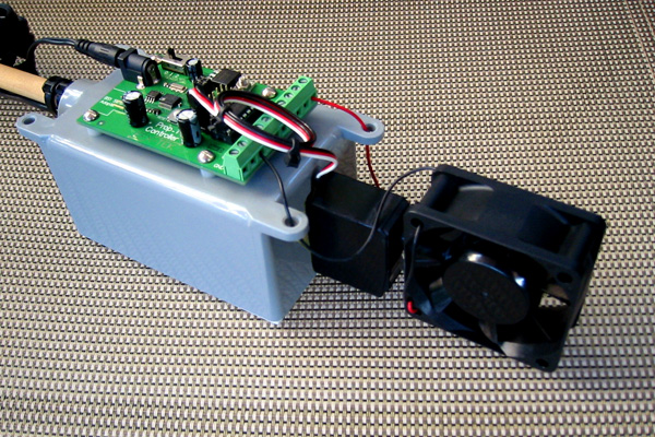 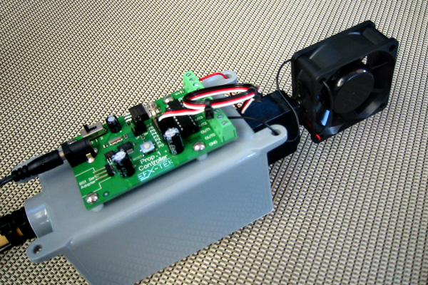 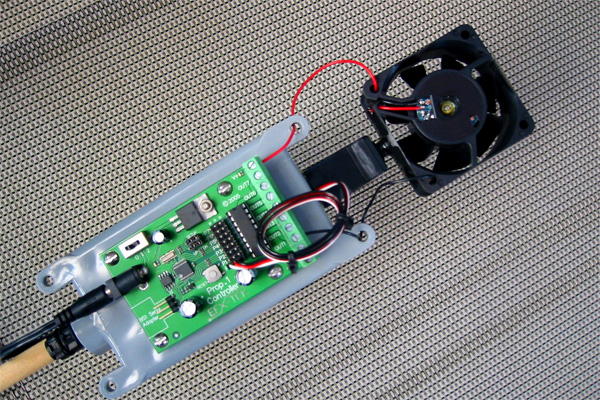 |
| They say a picture is worth a thousand words, well I am going to give you as many of both as I can! Let us start with a couple pictures of the moving variety in Windows Media (.wmv) format. (Note: some Mac/iOS users may require the free Flip4Mac plug-in to view the video content.) The first video shows the Floating Candelabra as it appeared during our 2006 Halloween season. As you will see the video camera does not do a particularly good job in the low-light environment, but it should suffice to convey the smooth, flowing animation of the prop... |
| Floating Candelabra (4.3 MB) |
| Launch video in external player |
|
Gee, perhaps I should have used a tripod... Hah!!! Oh well, live and learn. FYI: The audio track in the video is "Noctem Aeternus" from Midnight Syndicate's "Realm of Shadows" CD. One of the primary objectives I focused on while developing the Prop Floater was to create an animation that appeared organic and wandering instead of the obvious, repetitive pattern commonly seen when using a Flying Crank Ghost (FCG) type setup to float a candelabra. Please do not misunderstand, I am in no way criticizing the Phantasmechanic's FCG mechanism (or any other similar crank-type system) for use as a prop floating device; in fact, I suspect that for many haunts the FCG technique will prove to be the better choice. Heck, even Disneyland uses a motorized crank to fly their candelabra in The Haunted Mansion's endless hallway. However, for our haunt, an entirely different kind of animation was needed. I wanted the motion to appear as light and "floaty" as possible; fortunately, I knew just where to turn for inspiration! I have long been a fan of the now deceased Hallowed Haunting Grounds and have always enjoyed a particular fondness for their Floating Ghost Lantern (FGL) which was originally designed by Greg MacLaurin. You can view Brian & Karen Taylor's version of the FGL at: Kkrazy Kkaren's Floating Lantern Page In its simplest from, the FGL is basically a pair of counterbalanced levers suspended beneath a slowly rotating motor. This arrangement achieves the smooth, irregular motion I wanted to emulate; unfortunately, the FGL animation is limited to the horizontal with no appreciable vertical movement. I found myself wondering if there was any way to turn the whole thing on its side... |
| Prop Floater (6.4 MB) |
| Launch video in external player |
| (!) Please note that the above video is of the original/archived 2006 version of the Prop Floater, prior to receiving its Prop-1 update in 2009. |
|
How can a 25 gram mouse lift a 5 ton elephant? ~ OR ~ The exciting world of levers, fulcrums, and static equilibrium... A lever is a simple machine consisting of a bar supported at a stationary point along its length which is used to overcome resistance at a second point by application of force at a third point. The stationary point of a lever is known as its fulcrum. Static equilibrium is established in a lever when the sum of the forces acting on one side of the fulcrum multiplied by their distance from the fulcrum is equal to the sum of the forces acting on the opposite side of the fulcrum multiplied by their distance from the fulcrum. As a result, it is possible to counterbalance a very large force at a short distance with a very small force at a great distance. Having the lever in mind, Archimedes is supposed to have boasted that given an appropriate place to stand he could move the world. 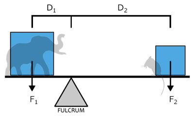 The above is in a state of static equilibrium with all forces balancing if (F1xD1)=(F2xD2). If we assume our elephant weighs 5 metric tons and is standing at a distance of 10 meters from the fulcrum, then our 25 gram mouse would need to have an exceptionally long lever of 2,000,000 meters (approx. 1,242.74 miles) to achieve a state of static equilibrium. Eeek, indeed! Of course this simplistic example ignores some real-world complications, not the least of which is the fact that a lever has to be made out of something and therefore contributes the weight of its own mass to either side of the equation... |
|
...Which brings me to my next dull-yet-mercifully-brief topic: Momentum. Thanks to Newton's classical Laws of Motion we know that all moving objects have momentum. The amount of momentum an object possesses is equivalent to the product of its mass and velocity, thus the greater the mass of an object the more energy is required to alter its direction of travel. If we set our oh-so carefully balanced lever into motion, its momentum must include the mass of the elephant, the mouse, and the lever itself. The greater the mass of the lever, the greater its momentum. This explains why, for the sake of building a properly functioning Prop Floater, we need to construct a lever that provides sufficient strength and rigidity while simultaneously contributing as little mass to the system as possible. In this instance, careful material selection is crucial! By the way, it is theoretically possible for a mouse to have the same momentum as a stampeding elephant! If our elephant friend was moving at a steady 5 kilometers per hour, the mouse would simply need to race along at a zippy 1,000,000 kilometers per hour (or 172.6 miles per second!) to achieve an equivalent momentum. What do theoretically stampeding mice have to do with the Prop Floater? Very little... they just make me laugh! |
Philosophiae Naturalis Principia Mathematica
|
Hey, what's with all this nonsense about levers, momentum and dead physicists??? As you saw in the Prop Floater video, this device consists of an animated mechanical lever suspended at a pivot point (or fulcrum) near its center, with a candelabra at one end, and a fan & motor assembly acting as a counterweight at the opposite end. If the lever remains unaffected by other forces, it soon achieves the boringly-harmonious state of static equilibrium... But we want this prop to move! The rotating fan, powered by a repeat cycle timer, provides ample force to keep the whole thing animated. It is important to understand that the total weight of the lever including the candelabra, fan & motor assembly as well as the physical lever itself needs to be as light as possible. Because the lever is in motion, a greater total mass will necessarily result in greater momentum and thus increase the difficulty of achieving the desired ghostly animation! The lever in my Prop Floater is made from aluminum tubing and I HIGHLY recommend using aluminum or another similarly strong, rigid and lightweight(!) material to anyone attempting this project. Does the entire Prop Floater need to be made from aluminum as mine is? No. The supporting framework is stationary and can be made from anything you wish, in some situations it may even be eliminated entirely; however, the choice of materials for the animated lever requires special consideration. |
Alright already, let's get to the nuts & bolts and have ourselves some prop-building fun! The construction details are divided into the following indexed sections:
Click on the index links above or simply scroll down. |
| MECHANICAL LEVER |
The mechanical lever is made from a 72 inch length of 5/8 x .093 round aluminum tube. You may find that you need a lever of a different length depending on the width of the window or display area in which you intend your prop to float. For the 32 inch opening of my window display this length works quite well. Drill a small hole through the exact center of the aluminum tube and attach a small hook-eye type bolt secured using a locking nut. The hook-eye is the pivot point (or fulcrum) of the lever. Eventually you will attach the hook-eye to the support frame's suspension beam using a heavy-duty fishing swivel. 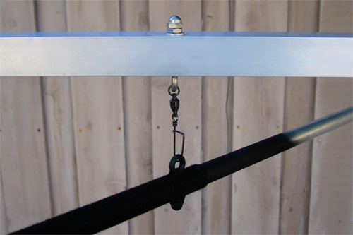 You may now paint the front half of the lever flat black or cover it with an appropriate length of black Duvetyne tape. I greatly prefer the Duvetyne because it is "flatter" than the paint and does not scratch off. If you are unfamiliar with Duvetyne, you may purchase it through various theatrical supply companies. See the Resources & Suppliers section. Next you will need two lengths of 7/16 inch poplar dowel. The long dowel should be cut to a length of 32 inches, the short dowel should be cut to a length of 8 inches. The dowels should fit quite snugly into the aluminum tube. The long dowel will be used to attach the fan & motor assembly to the counterbalance end of the lever and can simply be set aside for now. The short dowel will be used to attach a prop (in our case a candelabra) to the audience end of the lever and requires a bit more work... Pre-drill a small hole into the end of the short dowel and screw in a metal cup-hook. If you find that your cup-hook is too long you may simply cut, grind & shape the end of the hook using a dremel tool. Give the small dowel and hook a good coat of flat black spray paint and let dry. 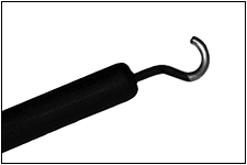 NOTE: The dowels are held in place within the aluminum tube simply by the snugness of their fitting. The dowels should slide in and out reasonably easily, yet without any extra looseness. If this is not the case, double-check that you have purchased the correct size aluminum tube and dowel. Also, be sure to avoid accidentally sliding the dowels completely into the aluminum or you may not be able to easily remove them. Seriously, trust me on this one... Return to Index |
(!) Please note that the following information references the original/archived 2006 version of the Prop Floater and does not pertain to the updated Prop-1 iteration. The following content is provided for archival purposes only. The current Fan & Servo information is available above in the August 12, 2009 UPDATE. 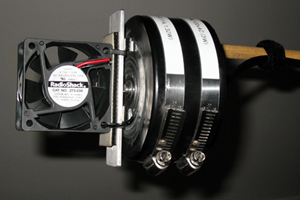 The fan & motor assembly is easily the most complex element of this entire project. It is important that you thoroughly understand how it is intended to work, so before we proceed I recommend that you watch the Prop Floater Video again paying particular attention to the "Fan & Motor" section... Did ya' watch it? Yes??? Ok then, let's continue.
Both of these items may require a bit of research to track down. This particular model of computer fan is frequently unavailable from Radio Shack's online store; however, their physical stores should still carry it. But no worries, there are plenty of other fans out there that will do the job equally well! Dynatron produces a nearly identical fan (Model: DF126025BL) which is available for purchase through CensusPC. The important things to remember are that you need a fan powered by 12vDC (for safety reasons which will soon become apparent), and that your fan should move approximately the same volume of air (14.5cfm) as the fan listed above. If you use a fan that moves a significantly greater/lesser volume of air, you will end up with a significantly different animation. Of course you should feel free to experiment with various fans and find the one that works best for you; however, an overpowered fan will easily ruin the ghostly motion we are trying to achieve while an underpowered fan will simply prove ineffective. The motor may be an even trickier acquisition. I purchased a small lot of timing motors from American Science & Surplus (AS&S) and recommend you start by looking there. The AS&S inventory changes frequently and it's always a bit of a crap-shoot as to what they will or will not have available. I have also seen these particular motors available on eBay, again something of a gamble. You can also try your luck at MPJA Online, another resource with a rotating inventory of interesting motors and electronic gadgets & gizmos. The best advice I can give is to remain persistant and just keep looking, eventually your tenacity will pay off. If anyone finds a reliable source for these motors, or a sufficiantly similar alternative, please let me know and I will happily list it here!
The black PVC end-cap needs to be the flat kind (not the rounded kind) as it will become the motor housing and fan base. Although this part has a 4 inch diameter, you will find it sold with the 3 inch plumbing parts. Drill a hole in the dead-center of the PVC end-cap just large enough for the motor's threaded shaft to fit through. Permanently attach the motor to the inside of the PVC end-cap using generous amounts of an appropriate metal to plastic 2-part epoxy. Do not(!) use screws to attach the motor, just the epoxy. Cut the electrical zip-cord into two 12 foot sections. It is important to use a highly flexible zip-cord as anything too rigid may adversely effect the motion of the lever. Attach a male electrical plug to the end of each cord. Permanently label one plug 12vDC and the other 120vAC. You may now use wire nuts to attach the 120vAC zip-cord to the 120vAC motor. Be sure all your connections are correct and safe before testing the motor! Unplug the motor after testing and before proceeding. WARNING: It is absolutely imperative that you never get these two electrical cords mixed up! As you saw in the video, the fan is constantly rotating on its horizontal axis. This means we cannot run wires directly to the fan or they will become twisted and entangled once the motor is engaged. Instead we will be using two flat nested metal rings to create positive and negative tracks upon which the fan can easily glide. The smaller ring must be large enough to fit around the opening for the motor shaft. The larger ring must be large enough to fit around the smaller ring. The rings must not be allowed to touch each other or the motor shaft. I spent a frustrating afternoon scrounging through numerous hardware stores before finding two rings that work. Both rings are flat metal gaskets. The smaller gasket was found in the electrical department and, if I recall correctly, was intended to be used in a gang box connection. The larger gasket was found in the plumbing department and is typically used in connecting a sink to a small drain pipe. If you are handy with metal you might find it easier to fabricate your own nested rings. As for me, I needed to search.
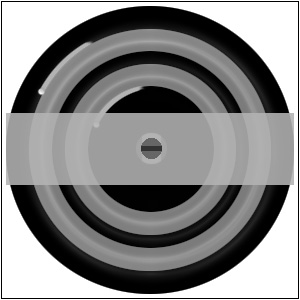 Create a sturdy mounting plate for the fan using a 4 inch length piece of 1 inch wide aluminum flat bar. Aluminum flat bar is almost ideal for this purpose and readily available at Home Depot. Carefully cut the aluminum using a chop saw, hack saw or dremel.
I recommend using the dremel to round over any sharp corners and edges.
Drill a small hole in the center of the mounting plate using a countersink bit. The exact size flathead screw you should use will depend upon the thread spacing within the shaft. My motor has metric sized threads and it took some searching to find an appropriately sized screw.
Attach the flathead screw into the mounting plate using additional epoxy. Be careful not to get any adhesive on the threads. Once dry, the mounting plate should screw easily onto the motor shaft.
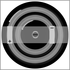 Using a pair of tin snips, cut two 1/4 inch wide x 2 inch long rectangles from the metal flashing. These will become the runners which connect the fan to the two 12vDC tracks.
Carefully fold the rectangles in half to create a sort-of V shaped spring. Your fan should have two wires coming from it. Solder one runner to the end of each wire and allow to cool.
Cut two 1/4 inch wide x 1 inch long strips of self adhesive 3M Dual Lock. This rigid velcro-like product is often used for electronics projects and is available from Radio Shack. The Dual Lock has a permanent adhesive backing on both sides.
Remove the protective film from one side of the Dual Lock and attach it to the top of one runner. Repeat using the other Dual Lock & runner.
Align the two runners so that one is over the positively charged track and the other is over the negatively charged track. Remove the remaining protective film from the Dual Lock and attach the runners to the underside of the mounting plate so that they maintain this relationship to the tracks.
The folded edge of the runners should be facing toward the motors direction of travel.
Securely attach the fan to the top of the mounting plate using additional Dual Lock and sturdy cable ties, then screw the mounting plate into the motor shaft. You may need to bend the lower half of the runners into a slight curve to maximize contact with the tracks.
Attach the black PVC cap to the 32 inch poplar dowel using two large pipe clamps. Tighten the clamps until securely fastened. Using small cable ties, secure the electrical cords within the PVC cap to each other so as to ensure they cannot be pulled loose. Attach both zip-cords to the dowel near the PVC cap with a large cable tie. Finally, slide the dowel into the unpainted end of the mechanical lever. Our finished Fan & Motor Assembly weighs 482 grams or 1 pound 1 ounce. Yours should weigh about the same. Return to Index |
Supplying power to the 4 RPM motor is as simple as plugging its 120vAC zip-cord into an extension cord connected to a standard household outlet. The motor should be allowed to run continuously during use. The fan must only ever be powered by a 12vDC source! Plug the 12vDC zip-cord into an AC to 12vDC adapter. These are readily available through Radio Shack, American Science & Surplus, and numerous other suppliers. To prevent the possibility of zip-cord confusion, you may choose to hard wire the 12vDC zip-cord directly to the power adapter.
Once complete, your power chain should look something like this:  Fine tuning the on-off settings for your RCT (or prop controller) can be fun, if a bit nit-picky. Don't be surprised if your fan spends considerably more time off than on. The goal is to provide just enough gentle persuasion to keep the prop animated. I encourage you to spend some time playing with various on-off settings, you will soon get a feel for how even small changes in timing can alter the animation. We eventually settled on a 16 second on, 40 second off interval. Because we want to encourage a certain amount of randomness in the Prop Floaters animation, it is important to be sure your RCT settings do not result in the fan repeatedly turning on & off at the same position over multiple rotations. In other words, if your motor rotates your fan exactly once every 15 seconds, you do not want to choose on-off intervals totaling 15 seconds or any multiple thereof: 30, 45, 60, etc... The best way to address this issue is to simply observe your fan over numerous cycles. If it repeatedly turns on at the same angle of rotation then you need to alter your RCT settings. Return to Index |
| CANDELABRA |
 Another one of the primary objectives I focused on while developing the Prop Floater was to create a device capable of floating a variety of different props. We just happen to float a candelabra; however, you may choose to float any prop you desire as long as it fulfills the following requirements... Appropriate Weight: The weight of your prop must be appropriate for this application. Too little weight will not enable you to achieve a proper counterbalance, too much weight will destroy the ghostly animation we are trying to achieve. Our candelabra (including the candles) weighs 588 grams or 1 pound 4.75 ounces. Connection Point: Your prop must have a secure connection point above its center of gravity. This point will connect onto the hook at the end of the mechanical lever, allowing the prop to hang vertically. As the end of the lever moves up and down the prop should not tilt, but instead should rise and fall without changing its vertical orientation. The connection point on our candelabra is a small metal ring inside the middle candle-holder. There is a narrow access groove cut into the back of the candelabra which allows the ring to be easily attached to the hook. Return to Index |
I can think of no better place to find an old candelabra than eBay. In fact, let's search now...
As a point of reference, I purchased a smallish pair of plain, brass candelabras for less than 10 bucks. Before you commit to any purchase you will want to be sure that it is size and weight appropriate. Our candelabra is 8.25 inches wide by 7.75 inches tall without candles or 13 inches tall with candles. The wax drip-plates, glass beads and faux-silver patina were added later. Return to Index |
Preparing the candelabra for use with the Prop Floater was quite simple. Using a dremel tool, I cut a narrow access groove in the back of the middle candle holder. Using a grinding bit, I smoothed the edges and corners. Next I attached a small ring to the inside of the candle holder using generous amounts of epoxy. The access groove allows the ring to be connected to the hook at the end of the mechanical lever. As I stated earlier, this connection point needs to be above the props center of gravity. INSERT RING/HOOK IMAGE HERE The remaining preparation was purely aesthetic... I purchased three wax drip-plates from a lamp parts store, one for each candle holder. I applied a faux-silver patina to the candelabra and drip-plates using a silver leaf product. The silver leaf is actually a composite of other metals and does not tarnish over time. A small amount of brass still shows through in a few places, but I quickly realized I liked the unusual textural look it created and decided to leave it that way. Next, I drilled six small holes equally spaced around the circumference of each drip-plate. Using beading wire I threaded some faceted glass beads onto each drip-plate through the small holes. Not only do these beads add nice detail to the prop, but they enable a secondary lighting effect which will be described in the Window Dressing section below. The candle holders on my candelabra are threaded so I was able to simply unscrew them, attach the beaded drip-plates, and screw the candle holders back on. It is unlikely that any two haunters will use the same candelabra; therefore, I cannot give explicit instructions how to prep your prop. Hopefully, reading how I approached this process will provide adequate detail to guide you. Return to Index |
The use of lit candles with this prop is strictly a no-no! Exposed flame in a haunt presents obvious safety issues; moreover, as candles burn they lose mass which is a recipe for disaster in a counterbalanced prop. Fortunately there are plenty of safe alternatives. You may simply choose to display a candelabra with unlit, drippy old candles that look as if they have been long extinguished. If you desire the look of lit candles you may either purchase electronic taper candles or simply make your own. I decided to make my own. One of the primary benefits of doing so was that I could choose exactly how tall I wanted each candle. This is a purely aesthetic concern, but one which mattered to me. Also, I already had the necessary parts so it was essentially free. I started with three tall, white taper candles. Using an old soldering iron I melted a groove down the back of each candle and removed the wick. Then I cut the candles to the desired lengths. Using a small jewelers screwdriver I carefully opened up three electronic votive candles I had stored from the previous Halloween. These are commonly available at stores like Target & Home Depot during the holidays and sell in packages of two for $1.99. The amber colored LED is already soldered directly to the small flicker circuit and is easily removed from the plastic votive housing. I simply wired these to a micro-switch and then to a battery holder, both available at Radio Shack. The whole thing was then embedded into the groove I had cut into the wax earlier, placing the LED near the top of the candle. Using generous amounts of white glue-stick and my trusty hot-glue gun, I sealed the LED circuit into place. The final task was to set the candles into their holders and slowly drip wax down the sides of each one to give the impression of use. I was careful to leave plenty of open space in the base of the middle candle to allow room for it to fit around the connection loop without blocking the access groove. The entire process took me a couple hours, but I suspect I work slower than most. 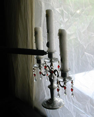 Return to Index |
| SUPPORT FRAME |
|
INSERT SUPPORT FRAME IMAGE HERE The support frame's primary purpose is simply to provide a stable & stationary attachment point from which to suspend the mechanical lever. Many haunts may already have appropriate locations to serve this purpose, rendering the support frame unnecessary. For example: you could cut a small hole in a theatrical flat and suspend the lever in such a way that the prop and blacked out front half of the lever are displayed on the audience side, while the rest of the lever as well as the fan & motor assembly are on the back-stage side. Personally, I like having an easily collapsible, portable, lightweight and sturdy support frame I know I can place in any location of my haunt. I suspect most home haunters will find the support frame beneficial. I provide the basic instructions necessary to build the support frame below; however, you should feel free to alter the materials and dimensions to best suit your haunts needs. NOTE: Even if you choose not to use the support frame, you will still need to facilitate secure locations to attach the Spring Limiter Assembly. Return to Index |
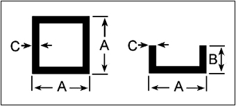 A=1 inch, B=0.5 inch, C=0.125 inch You will need two 84" lengths of 1" (A) x 0.125" (C) aluminum square tube, two 36" lengths of 1" (A) x 0.125" (C) aluminum square tube and two 54" lengths of 1" (A) x 0.5" (B) x 0.125" (C) aluminum channel. Additionally you will need 8 one inch wide metal "L" brackets, 4 one inch wide metal "T" brackets and assorted hex-bolts, washers, locking nuts and wing nuts. Although not absolutely necessary, a drill press will assist in drilling accurate holes in the aluminum tube.
Repeat this process to create the second leg. The second leg must mirror the first with the angled channel and "L" brackets facing the opposite direction of their counterparts from the first leg. Return to Index |
Cut two 36" lengths of 1" (A) x 0.125" (C) aluminum square tube. Mark and drill holes on either end of both lengths of square tube to align with the holes on the "L" brackets. These are the upper & lower horizontal connection beams. Connect the beams to the legs using hex-bolts, washers and wing nuts. These only need to be hand-tight. Remove these beams to collapse & store the support frame when not in use. Return to Index |
Cut one 36" length of 1" (A) x 0.125" (C) aluminum square tube. Attach four metal "T" brackets to the suspension beam, two on either end, using hex-bolts, washers and locking nuts. 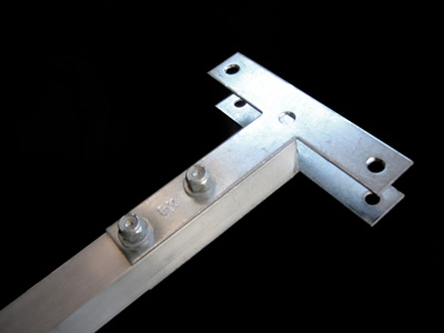 Drill a small hole through the center of the aluminum square tube and attach a small hook-eye type bolt secured using a locking nut. This hook-eye will connect to the hook-eye on the mechanical lever using a heavy duty fishing swivel. I suggest permanently connecting the fishing swivel to the suspension beam hook-eye. Using a pair of pliers, gently bend the hook-eye just enough to slip the fishing swivel into place, then bend the hook-eye back to its original position. Heavy duty fishing swivels are available at most sporting goods and fishing supply stores and look like this: 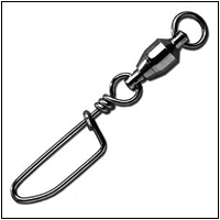 Place the suspension beam onto the legs so that the metal "T" brackets straddle either side of each leg. Secure the suspension beam using clamps. Be careful not to over tighten or you may deform the aluminum square tube. The suspension beam can be adjusted higher or lower allowing you to test the Prop Floater at various heights. Once you find the placement of the suspension beam that works best for you simply mark and drill holes on the legs to allow you to securely attach the suspension beam using hex-bolts, washers and wing nuts. I attached my suspension beam at a height of 56 inches. Return to Index |
| SPRING LIMITER ASSEMBLY |
|
The Spring Limiter Assembly (SLA) is a very simple yet entirely necessary component of the Prop Floater. Without it the mechanical lever would swing wildly outside the desired range of motion, eventually crashing into the Support Frame.
Careful placement and adjustment of the SLA will allow you to encourage greater vertical animation in your prop while controlling the horizontal range of motion. Return to Index |
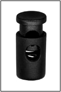 Adjust the placement of the small binder clip to increase or decrease the strength of the SLA. By connecting the SLA closer to the fulcrum, you decrease its ability to alter the mechanical levers motion. By connecting the SLA further from the fulcrum, you increase its ability to alter the mechanical levers motion. What you want is to find a connection point that allows the SLA to smoothly limit the mechanical lever's horizontal range of motion without any abrupt changes in direction or causing any swinging movement in the prop. By adjusting the height of the large binder clips which connect the spring lines to the legs, you can increase or decrease the amount of vertical movement imparted to the mechanical lever each time the lever reaches its horizontal limit. The closer you place the large binder clips to the horizontal plane of the mechanical lever, the flatter the props motion will tend to be. Return to Index |
| CONCEALING THE FRAME |
Having built the Prop Floater, the time had come to make sure no one would ever see it! I considered numerous ways to accomplish this task, and in the end I chose what seemed to be the simplest. I purchased a single flat, black, California king sized bed sheet at a local linens store during a sale. Using a sewing machine, I created a three inch long, vertical button hole in the sheet at just the place where the mechanical lever would protrude. I carefully slid the opening over the mechanical lever and draped the sheet onto the Prop Floater using large binder clips to attach it securely to the upper beam. That's it! 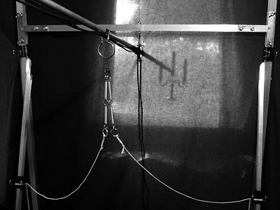 The sheet is invisible in the darkness of our haunt and it hides the Prop Floater (and anything behind it) perfectly. The only exposed element of the Prop Floater is the audience side of the mechanical lever which is already covered in black Duvetyne. With the proper lighting, neither the sheet nor the Duvetyne are visible. As is the case with many haunt effects, the lighting design can make or break the finished display. I often find myself repeating the haunters mantra: darkness is our friend, darkness is our friend, darkness is our friend... As I was thinking about the lighting design for the floating candelabra, I realized that by using a sheet I had created additional display possibilities. The sheet itself could act as a canvas for painting an "invisible" UV ghost effect, or it could support a series of fiber optics, or act as a projection surface, or... Well, you get the idea. The point is that the sheet can be more than purely functional, it can be used to add an additional layer of visual effect. Just remember not to do anything that may expose the mechanics of the Prop Floater. Return to Index |
| WINDOW DRESSING |
|
The first time I tested out our floating candelabra in its window I realized a few things.
First, I freakin' love the movement created by the Prop Floater!
Second, a finished prop placed in a bare window still looks unfinished.
Third, the candelabra prop seemed somehow too real, I needed a way to help it feel more ethereal. Its amazing what some simple window dressings can do... Return to Index |
Nothing says "creepy old haunted house" quite like decaying lace curtains! I found a pair of truly disgusting lace panels at a local $0.99 store that had probably been there for decades. Despite their obvious nasty-ness, they were still too white; fortunately, an overnight soak in a tea bath took care of that! I then lightly dusted them with a very small amount of flat dark gray spray paint to create a slightly singed look. These panels are used to frame either side of the window and help to convey the houses fiery past. Return to Index |
A very cool secondary lighting effect was created with the use of a large panel of silk organza. It is darn near impossible to see, but if you watch the Floating Candelabra Video closely you may notice that the candelabra appears to be surrounded by a swirling mass of tiny ghostly orbs. Pay particular attention to the close ups at the start and end of the video, ignoring the obvious head-light reflections from passing automobiles. The silk organza catches the light being reflected off of the glass beads. It also gives a slightly softening halo to the entire prop which creates a wonderfully ghostly feel. The organza is placed as close to the window as possible with the lace curtains behind it. To the guests the organza simply appears to be a very sheer window dressing which matches well with the old lace. We store the organza by wadding it up in a ball and placing it in a ziplock storage bag. This ensures lots of wrinkles and textural interest as well as numerous planes upon which to catch the reflected light. Return to Index |
 Thanks to Nathan at Turbidite Manor for introducing me to these cool LEDs! Return to Index |
| FINAL NOTES |
Assuming you have completed all of the steps above, you should now have a functioning Prop Floater & Floating Candelabra. I encourage you to spend some time exploring the various adjustments that can be made. Try changing the RCT settings or altering the SLA arrangement. How does the Prop Floater react to props of different masses? You will quickly get a feel for the benefits and limitations of the Prop Floater. Return to Index |
I am hoping my fellow haunters will use the information presented here as a starting point from which to find many creative ways to improve upon the Prop Floater. If you build any part of this prop, please share your experiences with the rest of us! I will happily include photos of other folks versions of the Prop Floater in future updates to this web page. Return to Index |
I wish to extend my sincere gratitude to the following folks for their inspiration, encouragement and support:  As a long-time fan of the Hallowed Haunting Grounds, I feel a debt of gratitude for their many years of inspired haunting! The Prop Floater was heavily influenced by Greg MacLaurin's wonderfully ambient Floating Ghost Lantern (FGL). The FGL was the first animated prop I ever attempted and remains one of my absolute favorite haunt effects! The show designers from the Hallowed Haunting Grounds have been quite generous with their creativity. Even after the shows retirement they continue to support the haunt community by sharing their abundant knowledge!  Nathan Hamilton, designer and owner of Turbidite Manor (and all-around awesome guy), introduced me to Luxeon LEDs and the idea of using these as a primary lighting source. This eventually led to the idea of using faceted cut-glass beads to reflect the LED light into a halo of ghostly orbs surrounding the Candelabra. Moreover, Nathan's haunt is wonderfully ghostly and a terrific source of inspiration to anyone fortunate enough to have the opportunity to experience it first hand! Jerry Chavez provided helpful feedback and encouragement in the creation of this how-to. Additionally, I wish to thank Jerry for sharing his wealth of knowledge about the art of visual effects and stage illusions with the haunt community. Lastly I want to thank the members of CalHauntS, Halloween-L, Howl2000 and the Garage of Evil for their seemingly inexhaustible supply of creativity and humor... You folks are frighteningly terrific! Return to Index |
| RESOURCES & SUPPLIERS |
Return to Index |
Return to Index |
This is not meant to be an exhaustive list of every possible commercial resource, nor is it an endorsement. These are simply vendors I have personally had a positive experience with. In particular, Studio Depot is a terrific source for colored gels and Duvetyne tape.
Return to Index |
The Ghost-Songs.com website is designed to be viewed with a browser implementing a majority of the CSS Specification!
Your browser does not fulfill these requirements. To enjoy the full experience of this website, please use one of the latest CSS compliant browsers.
For more information about CSS and CSS compliant browsers, visit the World Wide Web Consortium's (W3C) CSS Home Page at:
www.w3c.org/Style/CSS/. Thank you!
Copyright © 2004 - 2018, Ghost Songs Productions.
All Rights Reserved.